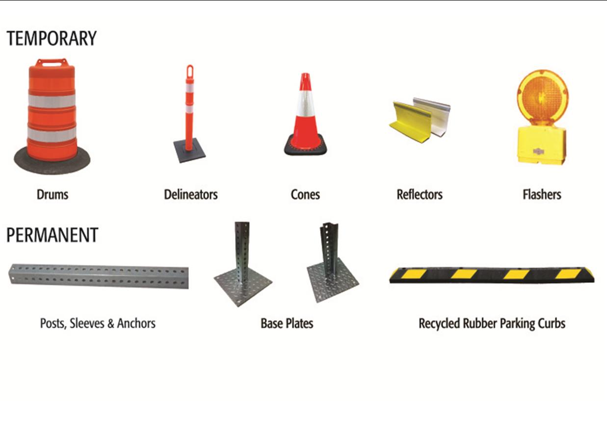
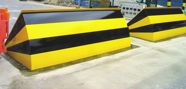
The Buzz on Wedge Barriers
In the complying with discussion, recommendation is made to a surface of a foundation to which the wedge-style obstacle is placed. As an example, in the detailed personifications, the top side of the support is significantly flush with the surface of the foundation. In such embodiments, the wedge-style barrier may be placed directly to the surface area of the structure. In other personifications, the top side of the anchor may be somewhat increased above the surface area of the structure or slightly recessed below the surface area of the structure. 1 is a front perspective view of a personification of a surface-mounted wedge-style obstacle 10. As shown, the barrier 10 is installed to a surface 12 of a structure 14(e. g., a shallow foundation ). The foundation
14 and the surface 12 to which the barrier 10 obstacle secured may protected made from concrete. 2, the barrier 10 is installed to or includes a support or subframe (e. g., support 30 received FIG. 2 )secured under the surface area 12. For instance, the bather 10 may be bolted to the anchor or safeguarded to the support by various other mechanical bolts. In the detailed personification, the obstacle 10 includes a wedge plate 16, that includes a section that is substantially parallel with the surface area 12 when the obstacle 10 is in the retracted position. To put it simply, automobiles or individuals may pass over the barrier 10 when the obstacle 10 is in the withdrawed position and experience mild elevation about the surface 12 while on the barrier 10. As gone over in detail below, when the barrier 10 remains in the released placement, the wedge plate 16 is held and supported in an elevated setting by a training mechanism of the barrier 10. In addition, the components 18 might be bolted or otherwise mechanically paired to each other. In this way, repair service or replacement of one or more parts 18 may be simplified and structured. That is, repair service or replacement of single components
18 might be done quicker, quickly, and cost properly. FIG. In particular embodiments, the anchor 30 might be a steel framework including plates, light beams(e. g., I-beams ), and/or other frameworks that are protected within the foundation 14, which may be concrete. At the surface 12, an upper side 28 of the support 30 may be at the very least partially exposed
, consequently allowing the add-on of the barrier 10 to the anchor 30. g., threaded holes)in several light beams or plates of the support 30 may be exposed to the surface area 12. In this way, bolts 32 or other mechanical fasteners may be utilized to safeguard the barrier 10 to the anchor 30. As the obstacle 10 is mounted to the surface 12 of the foundation 14, collection of particles and other product under the barrier may be decreased, and components of the bather 10 may not be exposed to listed below quality settings. As suggested official source by recommendation numeral 52, the training device 50 consists of components disposed underneath the wedge plate 16. For instance, the components 52 underneath the wedge plate 16 may consist of an electromechanical actuator, a this content web cam, one or even more web cam surface areas, and so forth. In addition, the training system 50 includes a springtime setting up 54
The springtime rod 58 is paired to a web cam(e. g., webcam 80 shown in FIG. 4) of the training device 50. The springs 60 disposed about the springtime rod 58 are kept in compression by spring supports 62, including a taken care of springtime support 64. That is, the fixed spring support 64 is repaired loved one to the foundation 14 et cetera of the bather 10.
Wedge Barriers Fundamentals Explained
g., spring assistance 65 )might be taken care of to completion of the springtime pole 58 to enable compression of the springtimes 60. As the springtimes 60 are compressed in between the spring sustains 62, the springtime setting up 54 creates a force acting on the cam combined to the spring pole 58 in an instructions 66. For instance, the continuing to be force put on
the web cam to release the wedge plate 16 might be offered by an electromechanical actuator 84 or various other actuator. The springtime assembly 54 and the actuator 84(e. g., electromechanical actuator)may run together to equate the cam read and raise the wedge plate 16.
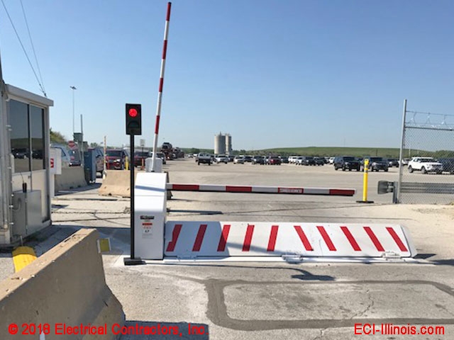
As discussed above, in the deployed placement, the wedge plate 16 offers to obstruct gain access to or travel beyond the barrier 10. The barrier 10(e. g., the wedge plate 16 )may obstruct pedestrians or automobiles from accessing a building or path. If an automobile is taking a trip towards the released wedge plate 16(e. For instance, in one condition, the security legs 86 may be expanded duringmaintenance of the barrier 10.